Tuesday, November 1, 2011

#4. CV and Advanced Routing


glödlampa

You might have heard the terms Gate and CV (control voltage) used in the synth terminology. They are basically signals used to control particular properties of a sound (for example - volume, filter frequency, pitch etc...). While gate has only two possible options - ON and OFF, the control voltage`s values can vary.

In previous tutorials we learned how the audio cables in Reason work. There is however one more type of cables used for the control voltage emulation. The cables themselves are tinier and do not connect in pairs for left and right like the audio ones. They have source and destination.

Let`s create two instances of SubTractor Analogue Synthesizer. Connect the first one`s audio out (it is mono device and has only one out) to the left input of the audio interface. Now connect the second one`s LFO1 output in the Modulation Output section to the OSC Pitch in the Modulation Input section of the first SubTractor. Now when you play the first one you gonna hear sound like a bird tweeting...

cv
In this picture we are using the first SubTractor to make the sound and the second SubTractor to control the first one`s oscillator pitch with it`s LFO1. The little knob determines the amount of the effect.

control voltage
You can adjust the properties of the LFO1 of the second SubTractor - the waveform, the ratio and the sync. Since we are using the LFO1 on an external device, the amount knob and the 6 destinations below are not being used.

What is basically happening is that the second SubTractor LFO1 is acting as the source of the CV signal, which controls the Osc Pitch of the first SubTractor as a destination. There is a knob near the input which determines the amount of the effect. You can experiment by routing different CV signal sources (LFO-s, envelopes, etc...) to different devices` various CV modulation inputs (pitch, frequency, amp level, etc.). Experiment with that, it is a lot of fun.

In this tutorial we are also going to cover some advanced routing. What if for example you want to use the same sound device outputs twice, or more? Do you need to create a copy of it with the same setting every single time? Well, NO, you just need to use a device called Spider Audio Merger and Splitter.

reason cv
On the left side it has four pairs of audio input channels for different devices and one single output where they all pass through. It is convenient if you want to link all of them to the same effects for example. On the right side is the audio splitter - it has one input for an audio device and four outputs, making basically four copies of it`s audio signal (with the same volume).

reason control voltage
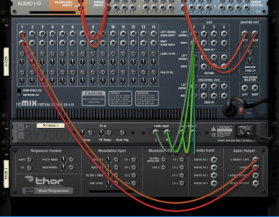
Splitting the signal of Thor, step 1 - routing it`s outs into the splitter ins.

advanced routing
Step 2 - we link the first splitter`s out back into the mixer. We than SHIFT create Scream 4 Distortion unit.

advanced routing reason
Step 3 - we link the second outputs of the splitter to the Scream 4`s inputs and then link it`s outputs to another channel of the mixer. As a result we have a dry Thor audio signal and another distorted one without the need to duplicate the Thor device.

routing in reason
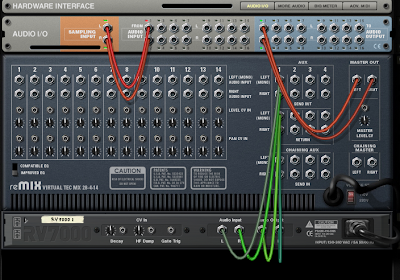
Example of audio merging - we link Thor and Malström devices to the Spider`s merger inputs and then link the left and right outputs to an Equalizer which is then routed to the mixer. That way we use a single EQ to effect two devices.

If for example you need more merger channels you can always connect the output to another spider merger input or if you need more splitter output channels you can save the last one to connect it to another spider. You can also merge signals, and then link their outs to the same spider splitter`s ins splitting that combined sound in four copies - all done in the same device.

There is also a Spider CV Merger and Splitter version which does exactly the same thing but this time with the CV. It has amount knobs on the merging side and two inverted outputs on the splitter side.

advanced routing
I strongly recommend experimenting further with those concepts. Route different CV sources to the CV merger and apply the output on different settings of some device, for example the Filter 1 Freq of the SubTractor. You can achieve some really wacky sounds by messing around. If you make a sound in a device (a.k.a. patch) that you like and you want to save it, click the diskette icon.

saving loading patch reason
Most of the devices have this patch browse - load - save function.

After you make sure that you understand the new material well, proceed to the next tutorial.

Friday, October 28, 2011

#3. Reason`s Mixers

reason mixer

In tutorial #1 Basic Audio Wiring we learned how to connect a device to the hardware interface. If you have a standard sound card like me, you may have already noticed that there is only one available pair of inputs for left and right signals, which can support only one device... So the question is - how can we link more devices to the hardware interface? Well, we need to use a mixer.

Open new empty rack and create Mixer 14:2. Connect it`s outputs to the inputs of the hardware interface. Now you have 14 brand new input channels for 14 new devices.

reason mixer connection
With the mixer linked up, we now have 14 different inputs for 14 different devices.

Each time you create a musical instrument it will automatically connect to the next free channel of the mixer. If you need more channels, simply link the mixer to another one as shown in the picture below (it will auto connect):

reason mixer connection
All you need to do is to connect master out to chaining master cables. There are four cables that also auto connect and they are for the aux send effects. You will read more about them below. Connecting them is optional.

Let`s look at the front of the mixer. On the lowest row we see 15 volume sliders - 14 for each device and 1 in the end for the master level. Above that we have a panning knob, which moves the signal from left to right in the stereo field. Above it we have Mute and Solo buttons. Then, above that we have an EQ section which can reduce or boost low frequencies (bass, set at 80Hz) or high ones (treble, set at 12kHz ). On the back, in the down left angle of the mixer you can switch between two different types of that EQ.

At last, on the top of the mixer`s front there are 4 red auxiliary send effects knobs.

reason mixer tutorial
1. Volume slider, 2. Pan knob, 3. Mute / Solo buttons, 4. EQ button with Treble and Bass knobs, 5. Aux send knobs with pre-fader button.

When we added an effect to Thor in tutorial #1, it was an insert effect, affecting the signal directly. The signal was flowing from Thor trough the effect to the hardware interface.

The send effect works differently. It mixes the original dry (unaffected) audio signal with a copy of it with the applied effect. To make an auxiliary send effect, just create an effect below the mixer (but not below another device) and it will link automatically. It`s outs will go into send out section and it`s ins will go into the aux section.

rv7000 aux
Linking an instance of RV7000 Advanced Reverb to the first aux send channel. We can now control the effect with the first of the four red knobs on the upper front of the mixer.

aux send tutorial reason
Make sound device, for example Thor and put it in the first channel of the mixer.

aux send
On the mixer`s front side bring the first aux send knob up a bit. Now when you play the sound of Thor you gonna hear the effect next to it.

We can have up to 4 send effects in a single instance of mixer 14:2 and use them on any of the devices linked to it. We control their amount with the red knobs on the top of the mixer. The small button, left from the lowest red knob switches the Pre Fader On/Off, basically leave it as it is on off and the ratio between the original signal and the affected one will stay the same when you make changes of the sound`s volume.

The red knobs on the top right of the mixer determine the return level of the effect.

We can use those effects in a technique that The Prodigy uses for example when creating beats called Parallel Compression, where you mix your beat signal with an overcompressed version of it (more about the compressor - later). We can also connect a chain of effects in the aux not just one.

When you create new mixer, the four chaining aux cables of the old one connect to the four aux channels of the new one. That way, the effects of the old mixer can be used in the new one too. If you wish to put new effects into the new mixer instead, do not connect those cables (but leave chaining master to master out connection as it is).

On the back of the mixer, below the input channels you can see smaller inputs...

mixer Reason cv
We will talk about them later, they are basically control voltage inputs which can use external signals to control the level and the panning of a particular channel. The little knobs determine the amount of the effect.

There is also another, simpler mixer called Line Mixer 6:2. It has only one aux send and lacks the level control voltage input on the back - it has only one for panning. The aux pre fader on/off option is on the back of the device.

line mixer
That`s basically all you need to know about the mixer. Make sure you understand the logic behind the connections then move to the next lesson.

Thursday, October 27, 2011

#2. Basic Synth Concepts

reason synths
We are now going to get familiar with the synthesizer and it`s components. The most important one is the oscillator. Every synth has one or more. It generates a waveform which we, humans, perceive as noise. It has frequency (cycles per second) and amplitude. The higher the frequency of the waveform, the higher the pitch we hear. Notes are nothing more than specific number of cycles per second - for example the A note above middle C has the pitch of 440 Hz. The amplitude on the other hand determines the loudness of the sound.

wave

am fm
The upper two pictures show the difference in amplitude which results in louder sound. The lower two show the difference in frequency resulting in higher pitch.


amplitude and frequency modulation


Amplitude and Frequency modulations

The subtractive synthesizers generally uses four types of waveforms - the sine, square, triangle and sawtooth generating different types of sound (note that some of the synths can have many more, for example Subtractor). Low sinewaveforms for example are pretty good for sub bass tones. The combination of different oscillators creates an unique sound.

sine, square, triangle, sawtooth waveforms
The filters are used to filter certain frequencies from the sound. The Low Pass Filter (LP) is used to filter high frequencies while passing the lower ones. The more it`s knob is positioned to the left (or down in the case of Subtractor, Dr Rex etc...), the lesser high frequencies are being passed. The High Pass Filter (HP) does the opposite. The Band Pass Filter (BP) passes only frequencies in between while the Notch Filter filters the middle frequencies (automating that is great for creating the Reese basses used in the drum and bass genre).

Reason filters
Filter and Resonance in Subtractor and Thor`s State Variable Filter


low pass, high pass , band pass, notch filters


The different types of filters. The frequency spectrum is presented horizontally (from low (left) to high (right)). The volume is presented vertically. The first filter keeps high volume for the low frequencies, and reduces it for the high ones. The second does the opposite - reduces the low frequencies. The third reduces the frequencies surrounding the center while the forth reduces the middle ones.


Resonance in simple terms is a boost near the cutoff frequency of the filters - the higher the boost, the lesser the Q (in other words... the horizontal thickness of the hill) and vice versa. Turning that knob up will add acidic property to the sound, it sounds great when moving the LP filter next to it.


q quality
Picture of resonance added to the cutoff of the low pass filter and the different types of "Q" depending on how high it is.

"Q" bandwidth visual
"Q" bandwidth visual... More about that when we discuss the EQ section. It describes the quality of the curve band passed by the filter.


LFO (low frequency oscillator) is a pretty low waveform (below 10 Hz, humans can`t hear it) which is used for controlling different parts of the synthesizer based on the waveform`s rule (loudness, pitch, filter frequency for tremolo, vibrato or sweep effects). It has amount and rate parameters (which can be tempo synchronized or key synchronized, the latter resets the LFO every time you trigger a note key). It has great variety of waveforms controlling the effect.

Low Frequency Oscillators in Reason
LFO examples in Reason


Another part of the synthesizer is the ADSR envelope. This abbreviation stands for Attack, Decay, Sustain and Release. It automates different properties of a sound (loudness, pitch, timbre). All of them are time parameters, except Sustain which is an amount parameter.


adsr filter
Thor`s amp envelope example (regulating the loudness of a sound)

attack decay sustain release parameters


ADSR envelope visual. The third parameter (Sustain) is always moving up and down horizontally since it is an amount parameter.


delay, attack, hold, sustain and release parameters


Thor has an advanced  DAHDSR filter.

Lets imagine that we use ADSR envelope to regulate the loudness of a sound...

Attack determines how long it will take for the sound to reach maximum volume after you hit the key on the keyboard. The higher the slider is, the slower the sound reaches maximum loudness (good for slowly progressing pads for example). If the slider is at it`s lowest point, the sound starts right away with full volume after hitting the key.

Decay starts right after the Attack has reached it`s maximum point. It fades the volume of the sound to the level set by the Sustain (the third slider). The shorter the Decay, the faster the sound diminishes to the level set by Sustain.

The Sustain level is the level of the sound you are going to hear as long as you keep the key pressed. If it`s slider is at it`s highest point, the Decay value loses meaning, since there is no lower value to decay to.

Release determines how long the sound is going to continue playing after you have released the key.

Synths have also Pitch Bending Wheel with Range determining option.

There is also a Mod Wheel thing. It`s purpose is to trigger the effects (set by different knobs) in the "Mod Wheel" section (or the nearest ones to it, in the case of the Subtractor).

Pitch Bend and Modulation Wheels in Reason

The Portamento is used when you want to gradually slide between the notes (bending the pitch so to speak).

You can select the amount of Polyphony (how many notes can the synth play in the same time) or you can make it monophonic by selecting Mono Legato (or set the polyphony to 1). Mono Retrig option does the same, but it also resets the envelopes every time you play a note, even if it flows into another one. The Release Polyphony determines how many notes can be playing at once when you have released the key.

Those are the basic synthesizer concepts. Make sure you understand them well before moving to the next lesson.


Friday, October 21, 2011

#1. Basic Audio Wiring

basic audio wiring in reason

Have you ever seen one those Moog modular monsters? One may ask himself: "What kind of crazy evil minded genius you have to be to know how this monstrosity works?". Well, the complexity is just an illusion - the whole system is composed of many, often repeated simple things. And the Propellerhead Reason wiring is no different.

Open a new, empty rack. Now the only thing you see is the Hardware Interface device on the top. This device is always presented and is basically the final destination of the audio signal. This is the device connected to your midi and audio hardware also you can use it as a connector to other programs (Like Fruity Loops Studio, Ableton Live, etc...) via ReWire.

The hardware interface has both Midi In and Audio Out devices (more about midi in and rewire - later...). For now, we are interested only in the Audio Out section. It transfers the audio signal to your sound card or rewires Reason to other programs.

Most probably, you are going to have only the first two audio output channels (one for the left and one for the right speaker) present, but you may have more depending on your sound card.

Reason Hardware Interface
The available channels are colored yellow, when you make the connection, they become green.

Now right click on the black area below and create Thor Polysonic Synthesizer (you can also create it from Create on the upper menu, or from the tool window accessed with F10).

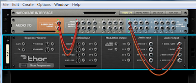
Hit TAB to look at the back of the rack. You can see that the output cables of Thor have been automatically connected to the input of the hardware interface:

thor connection
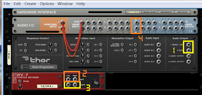
Now you can play the synthesizer with your keyboard or you can write notes in the sequencer (which is either below the devices and needs to be dragged up, or is using another window, if you have hit Detach Sequencer Window from the Window of the menu above). You might have noticed that the wiring has been made automatically (Reason always auto connects the newly created device to the nearest one), but you are often going to need to do the connection manually. Let`s try that. Right click and while holding shift create RV-7 Digital Reverb. OK, now look at the back of the devices again... You will see that because of the holding shift action the effect has not been connected automatically to the synthesizer. Our goal is to put some reverb effect on Thor - drag the cables from the Thor`s left and right outs and put them in the reverb`s left and right ins accordingly, then put the reverbs left and right outs back to the hardware interface`s ins. It is simple as that, now the effect is affecting the synthesizer successfully:

thor wiring
1 - The Thor`s outputs; 2 - The Reverb`s inputs; 3 - The Reverb`s outputs; 4 - The hardware interface`s inputs.

thor connection 1
The newly created reverb (by holding shift) is not connected automatically...

thor connection 2
When finishing the connection, this is the result you should get.

Let`s do another interesting thing. Begin with a new, empty rack (from File -> New). Hold SHIFT and create tree new devices - a Thor Polysonic Synthesizer, a RV-7 Digital Reverb. and a DDL-1 Digital Delay Line. Now put the left out of the Thor in the left in of the reverb. It will automatically connect both left and right cables, but you need to remove the right one.

thor connection 3
When you connect the left cable it automatically connects the right one as well...

thor connection 4
You need to remove the right one.

Then connect the left out of the reverb to the left in of the hardware interface. It will also connect both cables and you need to remove the right one again. As you may have guessed, we are going to create different effects for the left and the right outputs of Thor. Take the right out of thor and put it in the left input of the delay (you might intuitively put it in the right input, but it should be the left one), then connect the left out of the delay to the right input of the hardware interface. What you are going to get in result is reverb in the left speaker and delay in the right speaker.

thor
This is the final result you should get. Notice how even if we output the right cable of Thor, we still need to put it in the left input of the delay. Then we connect the left out of the delay to the right in of the hardware interface. Single cables are connecting always to the left channel of a device.

This is the basic audio wiring tutorial. You can connect all kinds of devices to different effects, than connect them into more effects, connect also only the right or lefts outs in different ones in an endless progression. All the devices have their inputs and outputs in similar places (if you can`t exactly see where they are in a particular device, create it without holding shift to see how it auto connects). Spend a little time experimenting with those concepts, be sure that you understand everything presented here well before moving to the next tutorial.

#0. Setting the program up

installing reason

I`m assuming that you know how to install a program so I won`t discuss that here. I have a Reason 5 installed on my PC, but don`t worry if you have a different version, the concepts are pretty much the same. When you start the program for the first time you will be asked what kind of audio driver would you like to use and what is your master keyboard type (if you use one).
Most probably, the defaultly selected audio driver will be DX Primary Sound Driver. You are OK using that, however I would recommend an ASIO one because it has lesser latency. If by some strange reason it is not in the list, you can download it for free. It may cause a common problem - it may stop your external audio (for ex. youtube clips) while you are using the program, or vise versa - it may stop the program`s sound while you are playing something external. I heard from some people that certain kinds of sound cards don`t have that problem, so the results may be different depending on your hardware setup. If you are using the PC`s built in sound card you are most probably going to experience that inconvenience... But again, I often use the default DX driver when I`m not using my keyboard.

The most common choice for sample rate is 44,100 (CD quality, you are perfectly OK with that).

If the program doesn`t detect your keyboard, you may select it manually from the list, or chose "OTHER". If you don`t have one, just chose "NOT SELECTED". You can always change any of those settings from the preferences menu of the program later.

Now, when the program finally starts, open the preferences and select Empty Rack in the Default song menu. That way you will have clean rack every time you open the program, without any of the demo songs loaded. You can set it up to open some custom template, things for example, that you commonly use in all of your projects. This can speed things up, removing the need to constantly repeat yourself making the same instruments and effects every time you create a new song. Another thing that you would wish to change is to remove the tick from Load Default Sound in New Devices. That will make all devices (instrument, effects) to be created in initialized mode every time you create one. Otherwise, you will have to always click on them and select manually "initialize patch" to remove the default setting, which I personally never use, so that things saves more time. Mouse knob range determines how precise can you select values while rotating any device`s knobs so you can change that depending on your taste. It is important to leave the tick on "Show Automation Indication" to see which knobs or sliders are automated (more about that later). Some people might want to change the master tune un the audio box to something different than the standard 440 Hz. There is a popular belief in the conspiracy circles that it is supposed to be 432 Hz (I personally can`t spot any significant difference, so I leave it as it is).

I think that should be all for the start up settings. You may explore further all the preferences and change anything else you like.